Saturday, 18 November 2017

FYP presentation day

WEEK 15:

 Final year project poster:


INDUSTRIAL DAY:


Alhamdulillah, thanks to allah s.w.t to give me chance to feel how to be a final year candidate and can continue my responsibility as a student. And also thanks to my FYP supervisor Madam Norhayati because always support and give all idea to make sure their student project will be more successful. During industrial day my also function as well and didn't have any problem and lastly thanks to all my friend who are give a full commitment to help my project to give and idea because this project is the last minute project. Without idea and information from my supervisor and friend in this project, maybe not be success. Thank You.      

Saturday, 11 November 2017

Prototype of the project

This is the last week to prepare all the project and to make sure all the system will be function as well.

                                   1] This part is to do wire ring all the bulb at home prototype.


2] All the system are completely construct and this project im also added the GSM to make this system is more modern.


 3] The project is already complete and system is function as well.


Friday, 3 November 2017

explain more about this new project

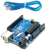
 On this project i will be used a Arduino UNO to control the whole system when someone is the piezo sensor it will be send signal to the Arduino UNO and the Arduino will be react to the other component to make this system is more secure.


After the Arduino detect the buzzer and all lamp or bulb will be automatically on around the house.
On this project also using a voltage regulator to maintain the voltage output connect with arduino.


Im already contruct and test the voltage regulator to get the maintain output to connect to the arduino. the voltage is 5V. And relay also used in this project, the relay type i used is relay 12V 4-channel. The relay already has been tested to connect to all the lamp or bulb. The connection bulb/lamp are in parallel.


Sunday, 29 October 2017

DEVELOPMENT OF HOME SECURITY SYSTEM USING PIEZO SENSOR


WEEK 12

From week by week my project to generate the energy by using piezo sensor is always have the problem. Which is the value of current is so small and the output is also cannot be maintain with this problem it is difficult to continue my project.


So, i already discuss with my FYP supervisor to change the title project. But this project is also using a piezo sensor but only just send a signal to the arduino. Now the official title for my FYP project is  DEVELOPMENT OF HOME SECURITY SYSTEM USING PIEZO SENSOR. And im also try my best to make sure this project are successful before the FYP presentation at week 15.


Tuesday, 3 October 2017

Energy Harvesting Circuit for Piezoelectric

Title: Energy Harvesting Circuit for Piezoelectric

Objective:
  1. To use this IC as main circuit for piezoelectric.
  2. To get stabilized output from piezoelectric.

Method:
  1. Make research and find data sheet for this circuit.
Result:
This breakout board uses the LTC3588 Piezoelectric Energy Harvester from Linear Technologies. This board can be used not only for harvesting piezoelectric energy, but solar energy as well. There is a bridge rectified input for piezo elements (PZ1 and PZ2) and a direct input (VIN) for DC sources. Both are clamped to 20V. In addition, the board can simply be used as a standalone nanopower buck regulator.
An ultralow quiescent current undervoltage lockout (UVLO) mode with a wide hysteresis window allows charge to accumulate on an input capacitor until the buck converter can efficiently transfer a portion of the stored charge to the output. In regulation, the LTC3588 enters a sleep state in which both input and output quiescent currents are minimal. The buck converter turns on and off as needed to maintain regulation.
Four output voltages (1.8V, 2.5V, 3.3V and 3.6V) are pin selectable with up to 100mA of continuous output current and comes pre-configured for an output of 3.3V. However, the output capacitor may be sized to service a higher output current burst. An input protective shunt set at 20V enables greater energy storage for a given amount of input capacitance.


Conclusion:
This circuit can be used in this project to make this project working effectively.

Tuesday, 26 September 2017

Learn more about PIC

I already study about PIC to use on my FYP project and this is one information i get from my study. this project maybe only just using program code digital voltmeter to detect value of voltage on my battery after i already charged the battery by using piezoelectric sensor.

sbit LCD_RS at RB4_bit;
sbit LCD_EN at RB5_bit;
sbit LCD_D4 at RB0_bit;
sbit LCD_D5 at RB1_bit;
sbit LCD_D6 at RB2_bit;
sbit LCD_D7 at RB3_bit;
sbit LCD_RS_Direction at TRISB4_bit;
sbit LCD_EN_Direction at TRISB5_bit;
sbit LCD_D4_Direction at TRISB0_bit;
sbit LCD_D5_Direction at TRISB1_bit;
sbit LCD_D6_Direction at TRISB2_bit;
sbit LCD_D7_Direction at TRISB3_bit;
int Adread;
float voltage;
char volt[4];
void main() {
PORTA = 0;
TRISA = 0X01;
PORTB = 0;
TRISB = 0;
LCD_Init();
ADC_Init();
LCD_Cmd(_LCD_CURSOR_OFF);
LCD_Cmd(_LCD_CLEAR);
LCD_Out(1, 1, “Digital voltmeter”);
delay_ms(1000);
while (1)
{
voltage = ADC_Read(0);
voltage = (voltage * 5 * 10)/ (1024);
inttostr(voltage,volt); // it converts integer value into string
Lcd_Out(2,1,”Voltage = “);
Lcd_Out(2,11,Ltrim(volt));
Lcd_Out(2,13,”Volt”);
}
}
source:click here

Monday, 25 September 2017

Buck Boost Converter

Title:
Step up voltage (DC-DC) module

Objective:
  1. Find suitable module to boost up the voltage.
  2. To fulfill the next objective for output. 

Method:
  1. Research from the internet (e-bay.com, lelong.com.my)
Result:

DC 3-34V to DC 4-35V DC-DC Adjustable Boost Step-up Power Supply Module
Description:
  • LM2577S non-isolated boost module
  • Input Voltage: DC 3-34V
  • Output Voltage: DC 4-35V (continuously adjustable)
  • Input Current: 3A (max.)
  • Output Current: 2.5A (max.)
  • Operating Temperature: -40 deg C to +85 deg C

Conclusion:
The output voltage can be vary from 4-35V DC and can be use for output.

Monday, 18 September 2017

Design circuit for bridge rectifier


From this circuit, i want to show the waveform the rectifier can convert from AC to DC and capacitor is to make the DC output more stable.

Thursday, 14 September 2017

Testing piezo-electric transducer

Title:
Testing piezo-electric transducer

Objective:
  1. To test the output of piezoelectric.
  2. To make the observation

Method:
  1. Connect 4 pieces of piezoelectric in series and parallel connection and record the output.
Result:

In parallel connection, the piezoelectric will produce about 2-16V AC depends on the mechanical stress that had been apply towards. But the output voltage is stable because of the mechanical stress is not the in the same amount of pressure.
If in series connection, it will step up the the voltage up to 24V AC.

Conclusion:
.The piezoelectric will produce the AC output voltage when the mechanical stress is apply.

Wednesday, 30 August 2017

FINAL YEAR PROJECT 2 S2 2017


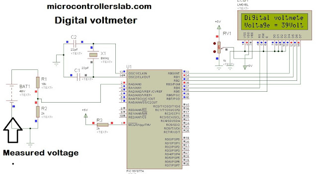
Alhamdulillah im already can procced for FYP 2 for this semester. 1st thing what im need to do for this FYP 2 is i need to learn how LCD on this project can display based on the value battery. LCD display must be start with microcontroller. So, im already find information for this microcontroler and based on my knowledge for microcontroller coding it should be use a digital voltmeter on microcontroller to detect the value from the battery. Im find the info is from the microcontroller lab web. 


Based on this picture it will be give some information for me to do design for this project on HOW TO DETECT VALUE OF VOLT ON BATTERY.

Friday, 2 June 2017

UPDATE NEW BLOG DIAGRAM


Based on previous blog diagram, i have a lot problem how to manage the process of this project. As example from previous blog diagram i use a ADC this project. We already know the function of ADC to convert analog to digital. so it is a big mistake for my project because on this project we did't need  the digital converter. But we just need to rectifier circuit because to make a current from piezoelectric sensor flow in one direction and to prevent the flow current back to piezo sensor.

Wednesday, 10 May 2017

FIND MORE INFORMATION ABOUT PIEZOELECTRIC SENSOR


Based on this research i can more information about piezoelectric sensor. for this link http://www.explainthatstuff.com/piezoelectricity.html i get a new information about piezoelectric sensor. How the Piezoelectric sensor works which mean how the piezoelectric sensor can produce from mechanical energy convert to electrical energy.

For this time i will simplify the process of piezo sensor works:

1. Normally, the charges in a piezoelectric are exactly balanced, even if they are not symmentrically arranged.

2. The effect of the charges exactly cancel out, leaving no net charge on the crystal faces. ( more specifically, the electricity dipole moment- vector line separating opposite charges- exactly cancel one another out.) 

3. if squeeze the crystal, the force will charges out of balance.

4. The effect of the charge ( their dipole moment) no longer cancel one another out and net positive and negative charge appear on opposite. 

5. So by the squeezing the sensor , it will be produce a voltage across its opposite faces. And that is called PIEZOELECTRICITY.

Tuesday, 2 May 2017

GENERATION OF IDEA BASED ON LITERATURE REVIEW


GENERATION OF IDEA


Based on all of journal that has found, it has some of info to use on this project. As example, for first journal is application of piezoelectric sensor and concept of piezoelectric sensor which is to convert mechanical energy to electrical energy. Other than that, piezo impact created is because of the adjustment in the electric polarization of the materials due to the apply stress which prompts the production of electric current or voltage. Next for second journal is for piezoelectric sensor have two type of effect which is direct piezoelectric effect and converse piezoelectric effect. Direct piezoelectric effect is the generation of electric charge when mechanical strain is applied on piezoelectric materials; whereas the converse effect is defined as the deformation in the crystal caused, when an electrical voltage is applied to the piezoelectric materials. Next journal is known about requirement for a wireless electrical power supply has impelled  an enthusiasm for piezoelectric energy collecting. So, all journal give a more knowledge and can apply on this project.

Friday, 28 April 2017

LITERATURE REVIEW


INTRODUCTION:

Electricity is a very important thing of our daily life. Without electricity it will be ruined our activities not just for ourselves but also for industrial. But lately, our populations also increase and the decaying of the natural resources energy crisis is becoming a very serious issue all over the world. As example on this crisis based on the whole world is we are dependent upon the fossil fuels for electricity. With a sort time maybe we can use this, but if it still using a fossil for electricity on a long time  it will be eliminated and soon they will be no longer available which is again very serious issue for our upcoming generation.    


JOURNAL 1:

There are a number of approaches being used to generate alternative power supply. One of the method is piezoelectric smart road sensor[1]. On application of mechanical stress on piezo materials equivalent amount of electric current or voltage is produced. This effect can be used in harvesting energy from the smart roads. Priyanshu et.al. says that when any vehicle moves on the roads it produces very small vertical deformations and vibrations on the roads. The increasing demand of the electricity forces us to think about harvesting that vibration energy from vehicles which is wasted otherwise. Also the traffic on the roads has increased to a certain level that if we employ such sensors on the roads it will be a great support in reducing the burden of the fossil fuels.
Energy can be harvested from various energy sources like radiations, light, temperature, vibrations etc. Vibrations are created from different sources like from machines in industrial, moving vehicles on streets and so on. Vibration to electrical energy is changed over by utilizing three distinct ideas i.e. Electromagnetic, Electrostatic and Piezoelectric[2]. The piezo impact created is because of the adjustment in the electric polarization of the materials due to the apply stress which prompts the production of electric current or voltage. The piezoelectric effect was proposed by the curie brothers according to which electric charge is produced, when force is applied parallel to polar axis using crystals of tourmaline, quartz, topaz, cane sugar and Rochelle salt[3]. Piezoelectric crystal are normally happening stable crystal until any outside forces are connected to them. Piezoelectric effect is a  reversible process. It can happen in two ways i.e. coordinate piezoelectric effect and speak piezoelectric effect.


JOURNAL2:

Another journal is [4] Some vibration based energy generators that converts mechanical energy to electrical energy that have been successfully developed are Electromagnetic[5], Electrostatic[6], Piezoelectric generators[7],[8]. There are two effects in piezoelectricity: direct piezoelectric effect and converse piezoelectric effect. Direct piezoelectric effect is the generation of electric charge when mechanical strain is applied on piezoelectric materials; whereas the converse effect is defined as the deformation in the crystal caused, when an electrical voltage is applied to the piezoelectric materials. Direct piezoelectric effect is employed in manufacturing sensors and converse piezoelectric effect is employed in manufacturing actuators. The piezoelectric materials are of natural and also of artificially made. Quartz is a natural piezoelectric material while Lead Zirconate Titanate (PZT) is an artificial piezoelectric material. PZT piezoelectric sensor can be used for small scale energy harvesting because of its high energy storage density[9].


         JOURNAL 3:

Other than that, for research journal is [10].The requirement for a wireless electrical power supply has impelled  an enthusiasm for piezoelectric energy collecting, or the extraction of electrical energy utilizing a vibrating piezoelectric device. Examples of applications that would benefit from such a supply are a capacitively tuned vibration absorber [11],a foot-powered radio “tag” [12], [13], and a PicoRadio [14]. Vibrating piezoelectric device varies from an average electrical power source in that its inner impedance is capacitive rather than inductive in nature, and that it might be driven by mechanical vibrations of changing amplitude and frequency.
On this journal described herein was to develop an approach that maximizes the power transferred from a vibrating piezoelectric transducer to an electrochemical battery. Other than that it is straightforward model of a piezoelectric transducer. An ac–dc rectifier is included what is more, the model is utilized to decide the purpose of ideal power stream for the piezoelectric element. To decide its power flowcharacteristics, a vibrating piezoelectric component is displayed as a sinusoidal current source ip(t)  in parallel with its inward electrode capacitance Cp.

Sunday, 16 April 2017

JOURNAL REFERENCES FOR PROPOSAL


1-) PIEZOELECTRIC SMART ROAD SENSOR

Link: PIEZOELECTRIC SMART ROAD SENSOR

Abstract from Journal:Energy harvesting is an emerging technology in order to meet the demands of the increasing population. Energy can be harvested from various sources like thermal, vibration, chemical etc. Similarly energy can be harvested from the roads by using the piezoelectric effect. This paper summarizes about the sensor that will be a great benefit to the lifetime of the fossil fuels and helps in preventing the environment from polluting due to wastes. This paper presents about the piezoelectric sensor that can be implanted beneath the road bed to harvest electricity from the vibrations produced due to the vehicles moving on the road.


2-) FUNDAMENTAL UNDERSTANDING OF PIEZOELECTRIC STRAIN SENSOR 


Info: Strain measurements from piezoceramic (PZT) and piezofilm (PVDF) sensors are comparedwith strains from a conventional foil strain gage and the advantages of each type of sensor are discussed,along with their limitations. The sensors are surface bonded to a beam and are calibrated over a frequency range of 5–500 Hz. Correction factors to account for transverse strain and shear lag effects due to the bond layer are analytically derived and experimentally validated. The effect of temperature on the output of PZT strain sensors is investigated. Additionally, design of signal conditioning electronics to collect the signals from the piezoelectric sensors is addressed.


3-) PIEZOELECTRIC ENERGY HARVESTING DEVICES: AN ALTERNATIVE ENERGY SOURCE FOR WIRELESS SENSORS

Info: One of the major limitations on performance and lifetime of WSNs is the limited capacity of these finite power sources, which must be manually replaced when they are depleted.Moreover, the embedded nature of some of the sensors and hazardous sensing environment make battery replacement very difficult and costly. The process of harnessing and converting ambient energy sources into usable electrical energy is called energy harvesting. Energy harvesting raises the possibility of self-powered systems which are ubiquitous and truly autonomous, and without human intervention for energy replenishment. Among the ambient energy sources such as solar energy, heat, and wind, mechanical vibrations are an attractive ambient source mainly because they are widely available and are ideal for the use of piezoelectric materials, which have the ability to convert mechanical strain energy into electrical energy.


Sunday, 2 April 2017

BLOCK DIAGRAM


METHODOLOGY:

Block Diagram


Piezoelectric Sensor:

A piezoelectric sensor is a device that uses the piezoelectric effect to measure pressure, acceleration, strain or force by converting them to an electrical signal. Other than that,piezoelectric sensor have  different type such as ceramic piezoelectric sensor and quartz crystal piezo sensor. But on this project will be use ceramic piezo sensor.  This project an array of 10 piezoelectric sensors is used for generation of power.

Lead Acid Battery:
Battery (electricity), a variety of electrochemical cells for electricity storage, either independently connected or exclusively connected and housed in a single unit. An electrical battery is a blend of at least one electrochemical cells, used to change stored chemical energy into electrical energy.

ADC (analog digital converter):
An analog-to-digital converter (abbreviated ADC, A/D or A to D) is a device that converts a continuous quantity to a discrete time digital representation. An ADC may also provide an isolated measurement. The reverse operation is performed by a digital-to-analog converter (DAC). Typically, an ADC is an electronic device that converts an input analog voltage or current to a digital number proportional to the magnitude of the voltage or current. However, some non-electronic or only partially electronic devices, such as rotary encoders, can also be considered ADCs.

Microcontroller:
This project uses the AT89S52 Microcontroller and Features of this microcontroller includes 8K bytes ROM, 256 bytes RAM 3) 3 Timers, 32 I/O pins, one Serial port, 8 Interrupt sources Here we are using AT89S52microcontroller to display the amount of battery get charged when we place our footstep on piezoelectric sensor.

Load:
Load on this project it mean output after the battery already charge and test the project using load. Load on this project can be use to charge phone, small fan and also can use a lamp or emergency lamp. 

Wednesday, 22 March 2017

WHAT IS FOOTSTEP GENERATOR USE PIEZO SENSOR


     Introduction:

Ability to produce electric power from mechanical reaction and then it change to electric charge. This kind of technology can be used as the alternative electric power generator. It is impossible to replace the existing electricity generation, but at least to vary and reduce the dependency on the conventional electricity generation.


Concept used:
  Design concept used in this project is to use piezoelectric place at the walking area named as “Foot Step Power Generation System”. When a human walking, jumping or dancing on the surface which contain the piezoelectric, it then will produce sufficient force for energy generation process.


      Target:

 This system is very suitable applied at the public spotted area with many people such as walking corridor, shopping mall, in the office, schools and others. Therefore, the continued pressure will provide sufficient resources to be used to produce the electricity required.

FYP presentation day

WEEK 15:  Final year project poster: INDUSTRIAL DAY: Alhamdulillah, thanks to allah s.w.t to give me chance to fee...