Saturday 18 November 2017

FYP presentation day

WEEK 15:

 Final year project poster:


INDUSTRIAL DAY:


Alhamdulillah, thanks to allah s.w.t to give me chance to feel how to be a final year candidate and can continue my responsibility as a student. And also thanks to my FYP supervisor Madam Norhayati because always support and give all idea to make sure their student project will be more successful. During industrial day my also function as well and didn't have any problem and lastly thanks to all my friend who are give a full commitment to help my project to give and idea because this project is the last minute project. Without idea and information from my supervisor and friend in this project, maybe not be success. Thank You.      

Saturday 11 November 2017

Prototype of the project

This is the last week to prepare all the project and to make sure all the system will be function as well.

                                   1] This part is to do wire ring all the bulb at home prototype.


2] All the system are completely construct and this project im also added the GSM to make this system is more modern.


 3] The project is already complete and system is function as well.


Friday 3 November 2017

explain more about this new project

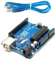
 On this project i will be used a Arduino UNO to control the whole system when someone is the piezo sensor it will be send signal to the Arduino UNO and the Arduino will be react to the other component to make this system is more secure.


After the Arduino detect the buzzer and all lamp or bulb will be automatically on around the house.
On this project also using a voltage regulator to maintain the voltage output connect with arduino.


Im already contruct and test the voltage regulator to get the maintain output to connect to the arduino. the voltage is 5V. And relay also used in this project, the relay type i used is relay 12V 4-channel. The relay already has been tested to connect to all the lamp or bulb. The connection bulb/lamp are in parallel.


Sunday 29 October 2017

DEVELOPMENT OF HOME SECURITY SYSTEM USING PIEZO SENSOR


WEEK 12

From week by week my project to generate the energy by using piezo sensor is always have the problem. Which is the value of current is so small and the output is also cannot be maintain with this problem it is difficult to continue my project.


So, i already discuss with my FYP supervisor to change the title project. But this project is also using a piezo sensor but only just send a signal to the arduino. Now the official title for my FYP project is  DEVELOPMENT OF HOME SECURITY SYSTEM USING PIEZO SENSOR. And im also try my best to make sure this project are successful before the FYP presentation at week 15.


Tuesday 3 October 2017

Energy Harvesting Circuit for Piezoelectric

Title: Energy Harvesting Circuit for Piezoelectric

Objective:
  1. To use this IC as main circuit for piezoelectric.
  2. To get stabilized output from piezoelectric.

Method:
  1. Make research and find data sheet for this circuit.
Result:
This breakout board uses the LTC3588 Piezoelectric Energy Harvester from Linear Technologies. This board can be used not only for harvesting piezoelectric energy, but solar energy as well. There is a bridge rectified input for piezo elements (PZ1 and PZ2) and a direct input (VIN) for DC sources. Both are clamped to 20V. In addition, the board can simply be used as a standalone nanopower buck regulator.
An ultralow quiescent current undervoltage lockout (UVLO) mode with a wide hysteresis window allows charge to accumulate on an input capacitor until the buck converter can efficiently transfer a portion of the stored charge to the output. In regulation, the LTC3588 enters a sleep state in which both input and output quiescent currents are minimal. The buck converter turns on and off as needed to maintain regulation.
Four output voltages (1.8V, 2.5V, 3.3V and 3.6V) are pin selectable with up to 100mA of continuous output current and comes pre-configured for an output of 3.3V. However, the output capacitor may be sized to service a higher output current burst. An input protective shunt set at 20V enables greater energy storage for a given amount of input capacitance.


Conclusion:
This circuit can be used in this project to make this project working effectively.

Tuesday 26 September 2017

Learn more about PIC

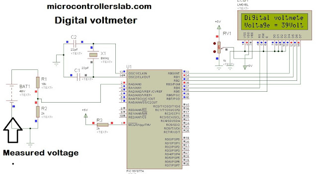
I already study about PIC to use on my FYP project and this is one information i get from my study. this project maybe only just using program code digital voltmeter to detect value of voltage on my battery after i already charged the battery by using piezoelectric sensor.

sbit LCD_RS at RB4_bit;
sbit LCD_EN at RB5_bit;
sbit LCD_D4 at RB0_bit;
sbit LCD_D5 at RB1_bit;
sbit LCD_D6 at RB2_bit;
sbit LCD_D7 at RB3_bit;
sbit LCD_RS_Direction at TRISB4_bit;
sbit LCD_EN_Direction at TRISB5_bit;
sbit LCD_D4_Direction at TRISB0_bit;
sbit LCD_D5_Direction at TRISB1_bit;
sbit LCD_D6_Direction at TRISB2_bit;
sbit LCD_D7_Direction at TRISB3_bit;
int Adread;
float voltage;
char volt[4];
void main() {
PORTA = 0;
TRISA = 0X01;
PORTB = 0;
TRISB = 0;
LCD_Init();
ADC_Init();
LCD_Cmd(_LCD_CURSOR_OFF);
LCD_Cmd(_LCD_CLEAR);
LCD_Out(1, 1, “Digital voltmeter”);
delay_ms(1000);
while (1)
{
voltage = ADC_Read(0);
voltage = (voltage * 5 * 10)/ (1024);
inttostr(voltage,volt); // it converts integer value into string
Lcd_Out(2,1,”Voltage = “);
Lcd_Out(2,11,Ltrim(volt));
Lcd_Out(2,13,”Volt”);
}
}
source:click here

Monday 25 September 2017

Buck Boost Converter

Title:
Step up voltage (DC-DC) module

Objective:
  1. Find suitable module to boost up the voltage.
  2. To fulfill the next objective for output. 

Method:
  1. Research from the internet (e-bay.com, lelong.com.my)
Result:

DC 3-34V to DC 4-35V DC-DC Adjustable Boost Step-up Power Supply Module
Description:
  • LM2577S non-isolated boost module
  • Input Voltage: DC 3-34V
  • Output Voltage: DC 4-35V (continuously adjustable)
  • Input Current: 3A (max.)
  • Output Current: 2.5A (max.)
  • Operating Temperature: -40 deg C to +85 deg C

Conclusion:
The output voltage can be vary from 4-35V DC and can be use for output.

Monday 18 September 2017

Design circuit for bridge rectifier


From this circuit, i want to show the waveform the rectifier can convert from AC to DC and capacitor is to make the DC output more stable.

Thursday 14 September 2017

Testing piezo-electric transducer

Title:
Testing piezo-electric transducer

Objective:
  1. To test the output of piezoelectric.
  2. To make the observation

Method:
  1. Connect 4 pieces of piezoelectric in series and parallel connection and record the output.
Result:

In parallel connection, the piezoelectric will produce about 2-16V AC depends on the mechanical stress that had been apply towards. But the output voltage is stable because of the mechanical stress is not the in the same amount of pressure.
If in series connection, it will step up the the voltage up to 24V AC.

Conclusion:
.The piezoelectric will produce the AC output voltage when the mechanical stress is apply.

Wednesday 30 August 2017

FINAL YEAR PROJECT 2 S2 2017


Alhamdulillah im already can procced for FYP 2 for this semester. 1st thing what im need to do for this FYP 2 is i need to learn how LCD on this project can display based on the value battery. LCD display must be start with microcontroller. So, im already find information for this microcontroler and based on my knowledge for microcontroller coding it should be use a digital voltmeter on microcontroller to detect the value from the battery. Im find the info is from the microcontroller lab web. 


Based on this picture it will be give some information for me to do design for this project on HOW TO DETECT VALUE OF VOLT ON BATTERY.

FYP presentation day

WEEK 15:  Final year project poster: INDUSTRIAL DAY: Alhamdulillah, thanks to allah s.w.t to give me chance to fee...