Sunday, 29 October 2017
DEVELOPMENT OF HOME SECURITY SYSTEM USING PIEZO SENSOR
WEEK 12
From week by week my project to generate the energy by using piezo sensor is always have the problem. Which is the value of current is so small and the output is also cannot be maintain with this problem it is difficult to continue my project.
So, i already discuss with my FYP supervisor to change the title project. But this project is also using a piezo sensor but only just send a signal to the arduino. Now the official title for my FYP project is DEVELOPMENT OF HOME SECURITY SYSTEM USING PIEZO SENSOR. And im also try my best to make sure this project are successful before the FYP presentation at week 15.

Tuesday, 3 October 2017
Energy Harvesting Circuit for Piezoelectric
Title: Energy Harvesting Circuit for Piezoelectric
Objective:
Method:


Conclusion:
Objective:
- To use this IC as main circuit for piezoelectric.
- To get stabilized output from piezoelectric.
Method:
- Make research and find data sheet for this circuit.
Result:
This breakout board uses the LTC3588 Piezoelectric Energy Harvester from Linear Technologies. This board can be used not only for harvesting piezoelectric energy, but solar energy as well. There is a bridge rectified input for piezo elements (PZ1 and PZ2) and a direct input (VIN) for DC sources. Both are clamped to 20V. In addition, the board can simply be used as a standalone nanopower buck regulator.
An ultralow quiescent current undervoltage lockout (UVLO) mode with a wide hysteresis window allows charge to accumulate on an input capacitor until the buck converter can efficiently transfer a portion of the stored charge to the output. In regulation, the LTC3588 enters a sleep state in which both input and output quiescent currents are minimal. The buck converter turns on and off as needed to maintain regulation.
Four output voltages (1.8V, 2.5V, 3.3V and 3.6V) are pin selectable with up to 100mA of continuous output current and comes pre-configured for an output of 3.3V. However, the output capacitor may be sized to service a higher output current burst. An input protective shunt set at 20V enables greater energy storage for a given amount of input capacitance.


Conclusion:
This circuit can be used in this project to make this project working effectively.
Tuesday, 26 September 2017
Learn more about PIC
I already study about PIC to use on my FYP project and this is one information i get from my study. this project maybe only just using program code digital voltmeter to detect value of voltage on my battery after i already charged the battery by using piezoelectric sensor.
sbit LCD_RS at RB4_bit;
sbit LCD_EN at RB5_bit;
sbit LCD_D4 at RB0_bit;
sbit LCD_D5 at RB1_bit;
sbit LCD_D6 at RB2_bit;
sbit LCD_D7 at RB3_bit;
sbit LCD_EN at RB5_bit;
sbit LCD_D4 at RB0_bit;
sbit LCD_D5 at RB1_bit;
sbit LCD_D6 at RB2_bit;
sbit LCD_D7 at RB3_bit;
sbit LCD_RS_Direction at TRISB4_bit;
sbit LCD_EN_Direction at TRISB5_bit;
sbit LCD_D4_Direction at TRISB0_bit;
sbit LCD_D5_Direction at TRISB1_bit;
sbit LCD_D6_Direction at TRISB2_bit;
sbit LCD_D7_Direction at TRISB3_bit;
int Adread;
float voltage;
char volt[4];
void main() {
sbit LCD_EN_Direction at TRISB5_bit;
sbit LCD_D4_Direction at TRISB0_bit;
sbit LCD_D5_Direction at TRISB1_bit;
sbit LCD_D6_Direction at TRISB2_bit;
sbit LCD_D7_Direction at TRISB3_bit;
int Adread;
float voltage;
char volt[4];
void main() {
PORTA = 0;
TRISA = 0X01;
PORTB = 0;
TRISB = 0;
LCD_Init();
ADC_Init();
LCD_Cmd(_LCD_CURSOR_OFF);
LCD_Cmd(_LCD_CLEAR);
LCD_Out(1, 1, “Digital voltmeter”);
delay_ms(1000);
while (1)
{
voltage = ADC_Read(0);
voltage = (voltage * 5 * 10)/ (1024);
inttostr(voltage,volt); // it converts integer value into string
Lcd_Out(2,1,”Voltage = “);
Lcd_Out(2,11,Ltrim(volt));
Lcd_Out(2,13,”Volt”);
}
}
source:click here
Monday, 25 September 2017
Buck Boost Converter
Title:
Step up voltage (DC-DC) module
Objective:
Method:
Step up voltage (DC-DC) module
Objective:
- Find suitable module to boost up the voltage.
- To fulfill the next objective for output.
Method:
- Research from the internet (e-bay.com, lelong.com.my)
Result:

DC 3-34V to DC 4-35V DC-DC Adjustable Boost Step-up Power Supply Module

DC 3-34V to DC 4-35V DC-DC Adjustable Boost Step-up Power Supply Module
Description:
- LM2577S non-isolated boost module
- Input Voltage: DC 3-34V
- Output Voltage: DC 4-35V (continuously adjustable)
- Input Current: 3A (max.)
- Output Current: 2.5A (max.)
- Operating Temperature: -40 deg C to +85 deg C
Conclusion:
The output voltage can be vary from 4-35V DC and can be use for output.
The output voltage can be vary from 4-35V DC and can be use for output.
Monday, 18 September 2017
Design circuit for bridge rectifier


Thursday, 14 September 2017
Testing piezo-electric transducer
Title:
Testing piezo-electric transducer
Objective:
Method:
Testing piezo-electric transducer
Objective:
- To test the output of piezoelectric.
- To make the observation
Method:
- Connect 4 pieces of piezoelectric in series and parallel connection and record the output.
Result:

In parallel connection, the piezoelectric will produce about 2-16V AC depends on the mechanical stress that had been apply towards. But the output voltage is stable because of the mechanical stress is not the in the same amount of pressure.
If in series connection, it will step up the the voltage up to 24V AC.
Conclusion:
.The piezoelectric will produce the AC output voltage when the mechanical stress is apply.
Sunday, 10 September 2017

Wednesday, 30 August 2017
FINAL YEAR PROJECT 2 S2 2017
Alhamdulillah im already can procced for FYP 2 for this semester. 1st thing what im need to do for this FYP 2 is i need to learn how LCD on this project can display based on the value battery. LCD display must be start with microcontroller. So, im already find information for this microcontroler and based on my knowledge for microcontroller coding it should be use a digital voltmeter on microcontroller to detect the value from the battery. Im find the info is from the microcontroller lab web.
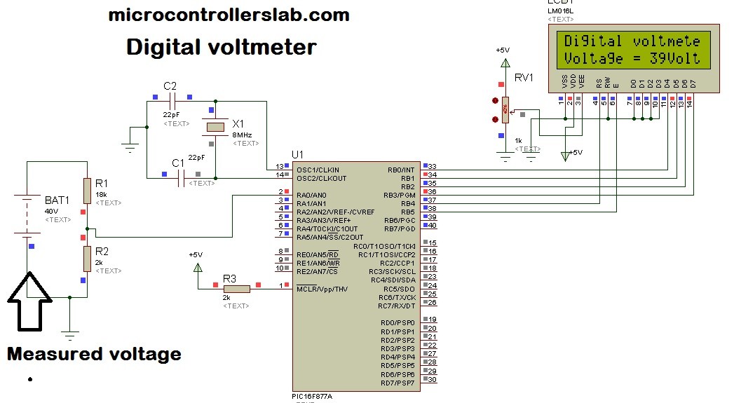
Based on this picture it will be give some information for me to do design for this project on HOW TO DETECT VALUE OF VOLT ON BATTERY.
Friday, 2 June 2017
UPDATE NEW BLOG DIAGRAM

Based on previous blog diagram, i have a lot problem how to manage the process of this project. As example from previous blog diagram i use a ADC this project. We already know the function of ADC to convert analog to digital. so it is a big mistake for my project because on this project we did't need the digital converter. But we just need to rectifier circuit because to make a current from piezoelectric sensor flow in one direction and to prevent the flow current back to piezo sensor.
Wednesday, 10 May 2017
FIND MORE INFORMATION ABOUT PIEZOELECTRIC SENSOR
Based on this research i can more information about piezoelectric sensor. for this link http://www.explainthatstuff.com/piezoelectricity.html i get a new information about piezoelectric sensor. How the Piezoelectric sensor works which mean how the piezoelectric sensor can produce from mechanical energy convert to electrical energy.
For this time i will simplify the process of piezo sensor works:
1. Normally, the charges in a piezoelectric are exactly balanced, even if they are not symmentrically arranged.
2. The effect of the charges exactly cancel out, leaving no net charge on the crystal faces. ( more specifically, the electricity dipole moment- vector line separating opposite charges- exactly cancel one another out.)
4. The effect of the charge ( their dipole moment) no longer cancel one another out and net positive and negative charge appear on opposite.
5. So by the squeezing the sensor , it will be produce a voltage across its opposite faces. And that is called PIEZOELECTRICITY.
Tuesday, 2 May 2017
GENERATION OF IDEA BASED ON LITERATURE REVIEW
GENERATION OF IDEA
Based on all of journal
that has found, it has some of info to use on this project. As example, for
first journal is application of piezoelectric sensor and concept of
piezoelectric sensor which is to convert mechanical energy to electrical
energy. Other than that, piezo impact created is because of the adjustment in
the electric polarization of the materials due to the apply stress which
prompts the production of electric current or voltage. Next for second journal
is for piezoelectric sensor have two type of effect which is direct
piezoelectric effect and converse piezoelectric effect. Direct piezoelectric
effect is the generation of electric charge when mechanical strain is applied
on piezoelectric materials; whereas the converse effect is defined as the
deformation in the crystal caused, when an electrical voltage is applied to the
piezoelectric materials. Next journal is known about requirement for a wireless
electrical power supply has impelled an
enthusiasm for piezoelectric energy collecting. So, all journal give a more
knowledge and can apply on this project.
Subscribe to:
Posts (Atom)
FYP presentation day
WEEK 15: Final year project poster: INDUSTRIAL DAY: Alhamdulillah, thanks to allah s.w.t to give me chance to fee...

-
 Title: Testing piezo-electric transducer Objective: To test the output of piezoelectric. To make the observation Method: Connect 4 pi...
-
 Alhamdulillah im already can procced for FYP 2 for this semester. 1st thing what im need to do for this FYP 2 is i need to learn how LC...